This project follows on from many previous.
We are going to assume we must make a system available on the internet but still maintain full protection.
(Convenience of administration is NEVER a reason for the above)
Background
Over time we have become accustomed to “connecting everything to everything using Ethernet/Internet”.
The main reason(s) appear to be: because:
– we want to,
– we can
or
– its what we always do.
The final activity is often “plugging network holes” (?) and making an insecure system workable (??).
ie. Security/protection is effectively an “add on” and always a “work in progress”.
The Project
We will use a Broadcast example to assist the discussion.
(1) The central routing switcher can provide a number of sources to a single destination.
(2) The control of the above destination must be from outside the facility using public infrastructure (internet).
(3) The external connection will only permit control of the one destination.
(4) The external connection will not enable any other access or control to any other internal resource or network.
(5) The worst that must happen is a DNS attack on the external connection.
(6) All external devices and interfaces are assumed to be hack-able or will be compromised at some time.
(7) If (6) occurs, then only the single destination is affected!
Important
– None of what follows is new, rather the application of techniques (discarded years ago) in favor of better (but less secure) alternatives.
(For those old enough to remember: punch cards, paper tape readers or terminals attached to main frames, they will find little new here.)
– If someone has physical access to the internal target system, all rules are off.
– One trade off with this approach is data rates, however such can be improved by various techniques (some are discussed).
Below is an overall (logical/abstract) view of the Project.
It’s possible to combine/split various sections as required, however this process can be complex and unique for each situation.
Architecture
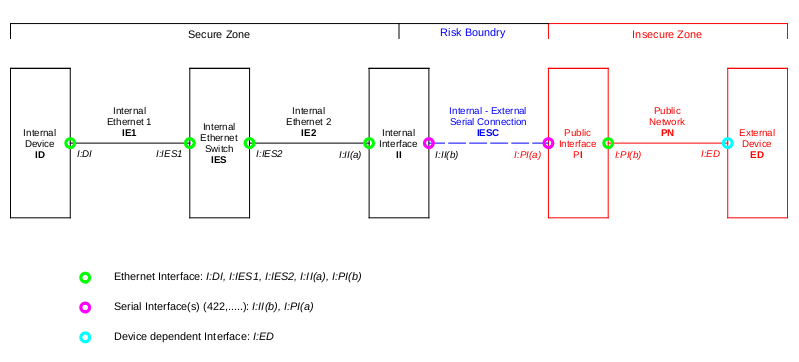
Architecture explained.
The approach is split into 3 areas, taking each in turn:
Secure Zone
All the devices / systems in this Zone are to be protected from the “Insecure Zone”.
All the hardware and signals are conventional.
If an attacker is already inside this Zone, the battle is (most) probably lost.
Risk Boundary
This is the point where the Insecure and Secure Zones meet.
It is typically the most critical area and must be constructed with care.
A major part of this project will investigate this Zone.
Insecure Zone
We will assume the worst in that we have limited or no control.
Devices and Interfaces – a few notes.
Before proceeding lets look at the devices in the system and broadly define their security requirements / limitations
Internal Device (ID)
Requirement: No command(s) received “directly” from the Insecure Zone can affect this system.
A simple way to think of this is that the ID and Insecure Zone speak different languages and require an interpreter to translate.
Tokenization is one way to achieve this and offers the following benefits:
Restricted vocabulary
Only tokens for permitted commands (etc) are defined and will be translated into valid commands.
The Insecure Zone can only achieve anything by using the defined tokens – everything else will be rejected.
Compression.
A plain text command “switch 5” is at least 7 characters, replacing “switch” with the character “^” gives “^5”.
So using the token approach our character count is reduced to 2, quite a saving if we have limited bandwidth.
Obscurity.
A plain text command “switch 5” will be quite obvious if it can be monitored.
However (following on from above), “^5” is far less obvious (or interesting).
A form of security when multiple connections are active.
Tokens can be used to pair devices.
We can gain a small measure of security if we make each Insecure Zone Client – ID connection use distinct tokens for the same function.
From above:
client 1: “switch 5” becomes “^5”
client 2: “switch 5” becomes “A5”
client 3: “switch 5” becomes “-5”
client 4: “switch 5” becomes “D5”
(there should be no overlap between the sets of tokens)
In the previous examples we only tokenized the string or characters.
Obviously its possible to do the same with numbers as well.
Doing this (using one scheme) would make the above example:
client 1: “switch 5” becomes “^r”
client 2: “switch 5” becomes “AW”
client 3: “switch 5” becomes “-l”
client 4: “switch 5” becomes “DP”
The location of tokenization and de-tokenization inside the Secure Zone requires considerable thought and care.
Tokenization is not foolproof, however it can be used to enhance security and provide some authentication.
There are many trade offs and it is impossible to provide “one rule that fits all situations”.
For example detecting the sharing of tokens is a problem to be addressed.
Restrictive measures:
In critical applications the ID can implement any number of measures to further assist the security:
time delays: control actions are all delayed by N seconds/minutes. this provides time for the ID operator to override same.
confirmation: the ID operator must confirm the action for it to take place.
timed lock outs: only at certain times can external actions be undertaken.
By way of (broadcast) example, consider the run up to a major OB.
(Not global properties, but tailored for each connection)
| Phase | Mode |
| Rig | Control actions instant and logged |
| Rig complete | Time delay added |
| Rehearsal | Confirmation required |
| On Air | Confirmation required or plug pulled! |
Internal Ethernet Switch (IES)
This is a standard switch, a managed variant is probably preferable.
It goes without saying that this network should be stand alone.
ie. If its possible to reach this switch from the Insecure Zone via another path…we are wasting our time?
Internal Interface (II)
We will delay comments on this (and its interfaces) until later as it forms a major part of this project.
Public Interface (PI)
As this device faces the Public Network it is vulnerable for all the usual reasons and is always a mix of usability vs security.
The major vulnerability it faces (using this approach) is Denial of Service.
We will delay further comments on this (and its interfaces) until later as it forms a major part of this project.
External Device (ED)
Assuming this is a PC / Mac / Android / I?, security will be considered adequate for the manufacturers purpose.
Of course that says nothing about suitability for anything else.
For this reason we have to assume it is, or will at some point in time be compromised.
2FA can be used to formerly associate ED with ID if required, with 2FA token provided verbally / ? and sourced from an unrelated system.
Examining the remaining interfaces.
Interfaces: I:DI, I:IES1, I:IES2, I:II(a), I:PI(b)
These are standard Ethernet interfaces and have all the advantages / disadvantages of same.
The flexibility of Ethernet is one of its strong points, but making a system attached to Ethernet secure can be complex and easily thwarted (innocent or malicious).
We have now examined most of the major sections (some only briefly).
Core concepts.
The final section is addressing the core of this approach.
Device II, Interface I:II(b), Device PI and Interface I:PI(b)
Is there anything can we do to improve security?
Starting with the Interfaces, what options exist?
Considering Ethernet firstly.
Ethernet layer.
Everyone seems to pay attention to IP, but its worth looking at the protocols defined on layer 2.
Its a vast zoo of potential problems (see one of our earlier projects).
So a major improvement might be to find an alternative?
Network interface card.
Its not obvious but many cards contain facilities to increase throughput and reduce the load on the CPU’s.
In doing so they can access critical parts of a computer without the CPU’s being aware or able to supervise/control.
For security this may not be a great idea?
Drivers.
Some sections of the driver must operate at the kernel or protected level of the operating system, hence require careful attention when security is of concern.
Again any bugs/problems at this level is a potential security hole.
IP based (or other) network stack.
IP(4/6) has made anything available on a single cable attached to our computer.
Its brilliant, but things we dont want can also arrive on the same cable and things we would rather keep inside our computer can disappear along it as well.
So if we could avoid the above it would also increase the security of our system.
What about Serial?
A major down side is a its slower and causes a sizeable reduction in data rate, but it comes with a lot of security upside.
(see later discussion on data rates – the results are interesting)
Contrasting it with the above
Serial interface or i/o card.
The external facing serial hardware contains nothing “exploitable” (apart from denial of service).
Although some cards may still contain facilities to assist the operating system.
The greatly reduced data rates makes the above less of a requirement as “on card buffering” is cheap and simple.
Drivers.
These are almost trivial and can be written by a good programmer.
Its possible on custom hardware it’s common to “roll your own” in assembler and C.
Network.
There is no networking to speak of.
Serial is very basic (electrically and packet wise).
It has nothing clever or difficult to observe.
Important
We are not suggesting anything clever like “ssh tunnels” or similar, rather stripping away all headers (and footers if present) and only sending the payload over the link.
Example: Using a UDP/IPV4 packet that would mean:
Ethernet Header and Check are removed.
IPV4 header is removed.
UDP header is removed.
Only the payload inside the UDP packet is sent over the link.
This effectively breaks the system into two unrelated parts.
Further, one side cannot increase its capability, perform any actions or affect the other side without the assistance of the other side.
This makes the external connection useless for anything but our application.
So we have the trade off:
Serial is useful (albeit with reduced bandwidth) to improve security.
Security.
We now need to secure the path from ID to ED.
(could be reduced to II to ED if required).
As we have a very limited connection (serial with only payload data) we cannot make use of any clever “network tools”.
Doing so would require this to occur with the PI, which we have assumed will be comprimised at some time.
Rather we will have to use “Public Key” or other “key generation techniques” exclusively.
There are plenty of references to these so we will not comment any further.
Wrapping up and a few final bits.
We have created a highly limited external interface.
Tokens are used to restrict the capability.
Information flow over the interface is minimal.
The payload is encrypted.
It is not possible for anything external to achieve anything other than what it has been permitted (no escalation or expansion of capability)
If the external end point is compromised, the above applies.
An aside – Data reduction
We indicated in the above that tokens (and the like) could reduce the traffic load and thus offset (very slightly) the reduced data rate available.
Before looking at that lets attempt to answer the question: “How much traffic is actually needed through my Ethernet connection?”
This is where Wireshark is very illuminating, particularly when comparing different operating systems (O/S).
Some O/S are very quiet and generate little traffic unprompted, others are endlessly chattering about “things” or looking for an update.
Then there are the applications…
How often does a virus checker need to call home, the browser “do things” whilst you read a page….the list goes on.
So if we didn’t have all the noise, could we live which much less bandwidth? Probably yes…
Hence by only allowing “real traffic” we are preserving the bandwidth for important functions.
Lets now look at some graphs and things.
As always there are lots of definitions, many are just there so you can play with them and observe the results (if desired)
Bb: Bits per Byte = 8 (We will assume a Byte (8 Bits) is the minimum data size)
Ps = 1 (Serial Connection: Min Bytes per Packet)
Pe = 82 (Ethernet Connection: Min Bytes per Packet)
To obtain this:
Ethernet Frame (Header, min payload = 64 Bytes and Check) = 6 + 6 + 2 + 64 + 4 = 82 Bytes
Where the Payload is:
IPV4 Packet = 20 Bytes + Payload (the UDP Packet)
UDP Packet = 8 + Payload
The above is a minimal frame with least possible options.
Finally, the space available in the UDP Packet for our data = 64 – 20 – 8 = 36 Bytes
Lets see how things look when we start sending 1 Byte and increase.
Another couple of definitions:
Cs(n): Serial Bytes required for message length n.
Ce(n): Ethernet Bytes required for message length n.
For a message of length n, how many bytes will it consume “on the wire”?
For Serial:
Cs(n) = n
As the basic size is a Byte, each Byte we add will make the Message longer.
But for Ethernet its a little more involved:
Ce(n) = 82 (where 0 <= n <= 36)
Ce(n) = 82 + (n – 36) (where: 36 < n)
As we can see the Packet size for Ethernet is fixed until the payload must be expanded.
So for small “n” Ethernet it very wasteful, but as “n” increases the wastage is reduced.
This can be illustrated by calculating: Ce(n) / Cs(n): the ratio of Packet Sizes.
The easiest way to understand the above is via a graph (below).
(The python code is included at the end.)
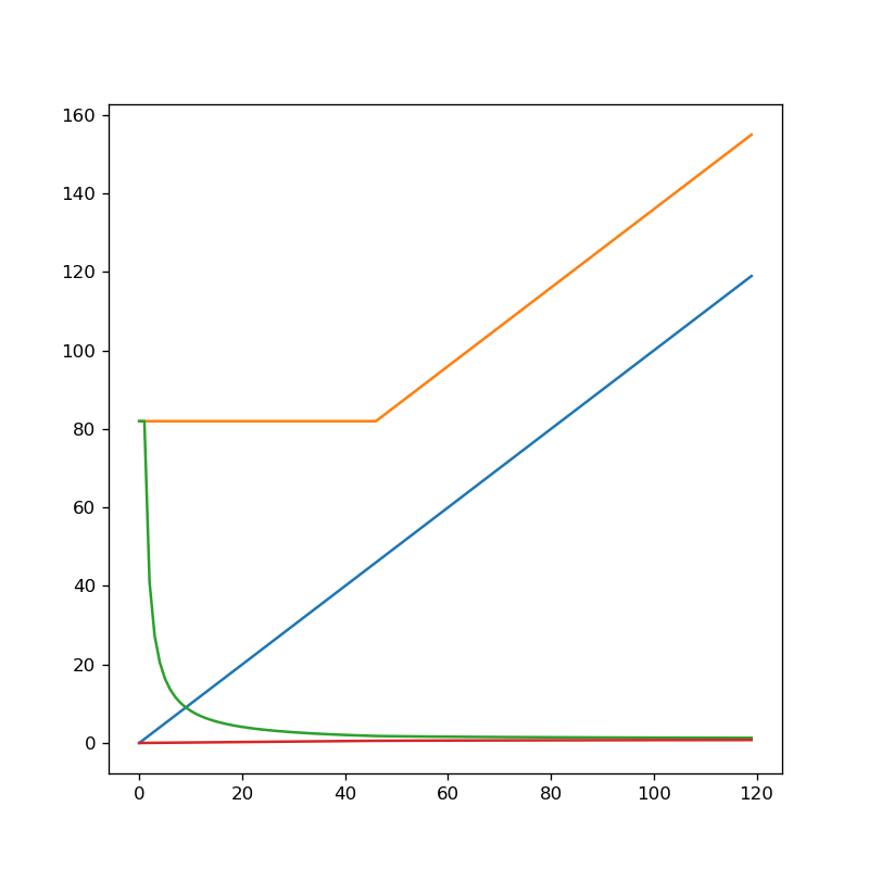
The horizontal axis is message length in bytes.
The vertical axis is packet length sent in bytes.
The blue line is the serial connection.
Its easy to see how as each byte is added, the message sent gets longer.
The orange line is the Ethernet connection.
Observe how it is constant until the payload size must be increased (at 36 Bytes).
The green line is the ratio of the packet sizes and indicates the saving by using Serial rather than Ethernet.
Observe how for small Packet sizes the Serial Connection is very efficient….
As the Packet Sizes increase the savings reduce and tend to the same value.
The Python Code….
#created using jupyter notebook with a ipython kernel

import matplotlib.pyplot as plt

dpi = 120

PLenE = 82 # min packet len for Ethernet
BAvailE = PLenE - (64 - 20 - 8)

MaxN = 120

Ce = []
Cs = []
Res = []
Rse = []

fig = plt.figure(figsize=(800/dpi, 800/dpi), dpi=dpi)

def MakeC():
    global Cs, Ce, Res, Rse

    Cs.clear();
    Ce.clear();
    Res.clear();
    Rse.clear();

    # create all the lists
    for i in range(0, MaxN):

        # create Comms bytes for SERIAL
        Cs = Cs + [i]

        # create Comms bytes for ETHERNET
        if (i <= BAvailE):
            Ce = Ce + [PLenE]
        else :
            Ce = Ce + [PLenE + (i - BAvailE)]

        # create Ratio: Serial / Ethernet
        if (i == 0) :
            Res = Res + [PLenE]
        else :
            Res = Res + [Ce[i] / Cs[i]]

        # create Ratio: Ethernet / Serial
        Rse = Rse + [Cs[i] / Ce[i] ]

    plt.plot(Cs)
    plt.plot(Ce)
    plt.plot(Res)
    plt.plot(Rse)
    fig.savefig('bit_rate_reduction.png')

MakeC()